Status : Completed
Tags: arduino servo Adafruit c++
The aim of this project is to design and build a basic spider robot that can move and navigate on flat surfaces.The end goal of this project would be to create a functional and reliable spider robot t
arduino
c++
servo
Adafruit
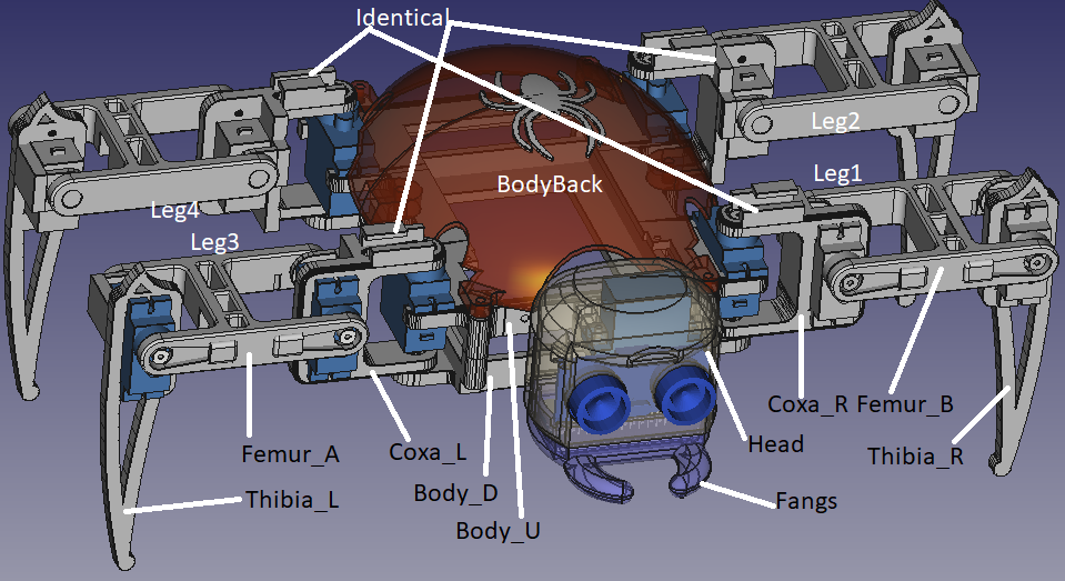
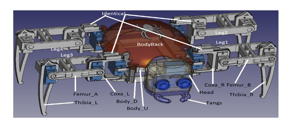
SPIDER BOT PARTS-
1. Arduino Nano Board:
The Arduino Nano is a compact and versatile microcontroller board. It serves as the brain of the Spider Bot, responsible for processing instructions, controlling servo motors, and coordinating the overall motion.
The Nano's small form factor makes it suitable for robotics projects, providing a balance between functionality and size.
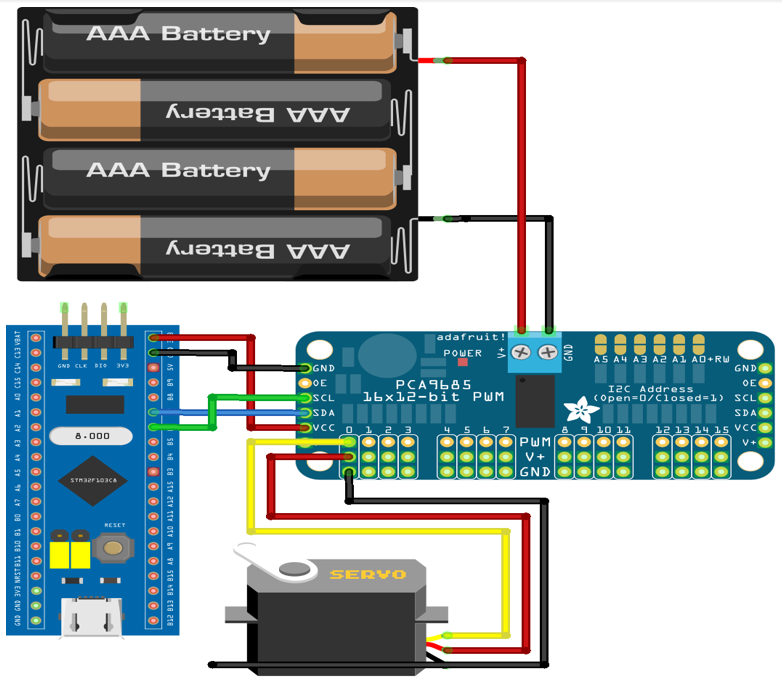
2. Adafruit PWM Servo Driver:
The Adafruit PWM Servo Driver is a dedicated controller for managing multiple servo motors. It simplifies the process of controlling a large number of servos simultaneously, as it extends the limited number of PWM pins on the Arduino. This component is crucial for managing the numerous SG90 Mini Servo Motors used in the Spider Bot.
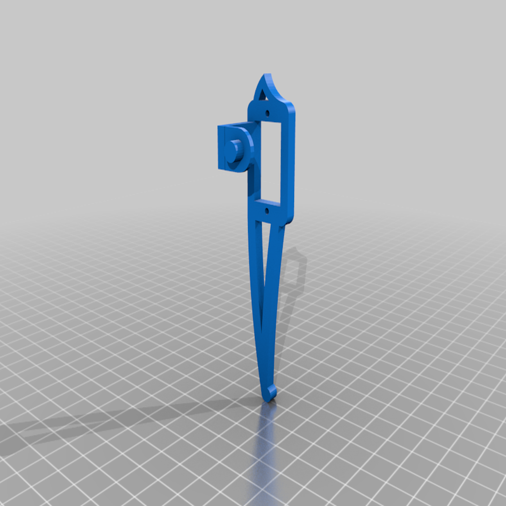
3. SG90 Mini Servo Motor (12):
The SG90 Mini Servo Motors are compact, lightweight motors with the capability to rotate within a specific range. In the Spider Bot, these servos actuate the various joints and limbs, enabling precise control over the movement of each leg. With 12 servos in total, distributed across the legs and body, they play a central role in achieving the spider-like motion.
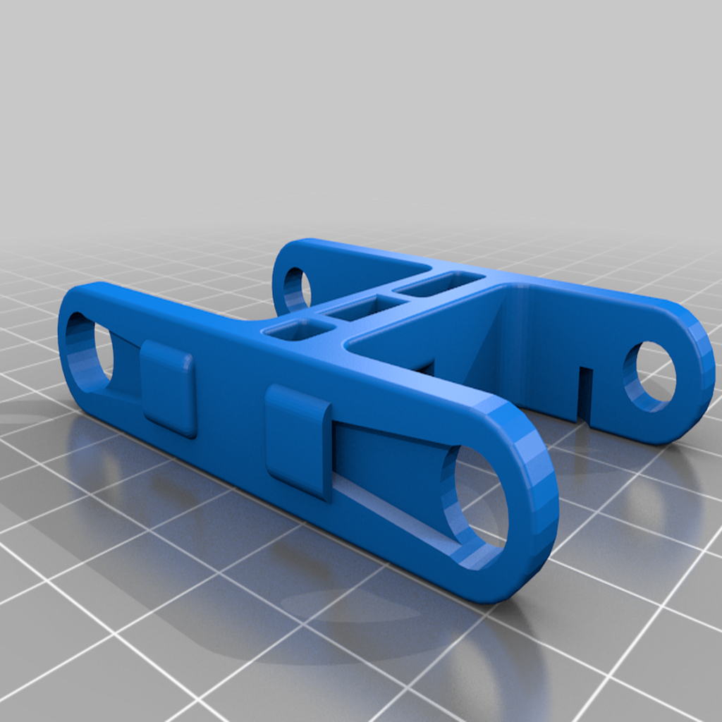
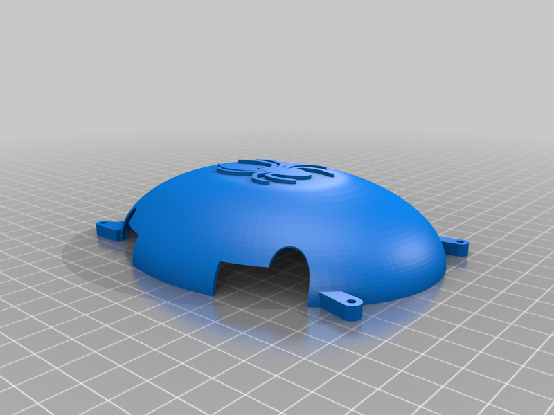
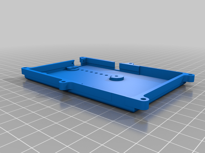
4. Chassis and Legs:
The chassis forms the structural framework of the Spider Bot, providing support for attaching the servo motors and legs. The legs are designed to mimic the multi-jointed structure of a spider, facilitating agile and stable locomotion. The combination of a well-designed chassis and articulated legs contributes to the overall stability and functionality of the Spider Bot.
5. Power Supply (Battery):
The power supply, typically in the form of a battery, provides the necessary electrical energy to drive the Arduino Nano, Adafruit PWM Servo Driver, and the servo motors. The choice of an appropriate power supply is crucial to ensure that the Spider Bot operates reliably and has sufficient power to drive all its components during various movements.
6. Jumper Wires:
Jumper wires are used for establishing electrical connections between different components on the breadboard or within the circuit. In the Spider Bot, jumper wires play a vital role in connecting the Arduino Nano, PWM Servo Driver, and servo motors, enabling the seamless flow of control signals and power.
These components work in tandem to create a sophisticated robotic system. The Arduino Nano processes control signals, the Adafruit PWM Servo Driver manages servo motors efficiently, and the SG90 Mini Servos drive the leg movements, collectively contributing to the Spider Bot’s dynamic and lifelike motion. The chassis and power supply provide the structural and electrical foundation for the entire system, while jumper wires facilitate the necessary connections to ensure smooth communication and operation.
The Spider Bot’s motion and functionality are achieved through a combination of trajectory planning, inverse kinematics, and the coordinated movement of its servo motors. Below is an elaboration of its working:
Initialization and Setup:
Standing Position:
Walking Steps:
The walking cycle involves a series of steps, and each step is described as follows:
Leg Movement: The robot bends its knees, allowing one leg to swing above the ground while the other supports its weight.
Body Tilt: The upper body tilts in the opposite direction to provide enough height for the swinging leg.
Leg Placement: Both legs are placed on the ground to support the robot for further walking steps.
Leg Swing: The free leg swings forward, and the hip center trajectory is controlled using trajectory planning equations.
Body Re-Centering: Both legs come together, and the body re-centers to its normal standing position.
Trajectory Planning:
Inverse Kinematics:
Turning and Shifting:
Walking Sequence:
The Spider Bot executes a sequence of leg movements, including lifting, swinging, and placing, to achieve forward motion. Coordinated movements of all legs are orchestrated to mimic the walking cycle.
User Interaction:
Power Supply and Components:
The Spider Bot is powered by a battery, and its components include an Arduino Nano, Adafruit PWM Servo Driver, SG90 Mini Servo Motors, chassis, legs, and jumper wires.
In summary, the Spider Bot’s intricate motion is achieved through a combination of precise trajectory planning, inverse kinematics, and coordinated control of its servo motors. The provided code defines various functions and sequences that enable the Spider Bot to exhibit lifelike movements, resembling the walking pattern of a spider.
Steps involved:
Setup:
Basic Motions:
Inverse Kinematics Functions:
Trajectory Generation:
Center Shift and Turn Functions:
Walking Algorithm (moveBot):
Serial Communication:
Testing and Debugging:
Trajectories for Spider Bot:
Trajectory planning is instrumental in orchestrating the motion of the Spider Bot, dictating a sequential series of joint angles over time to seamlessly transition the robot from an initial configuration to a goal configuration, effectively accomplishing various tasks.
Trajectory Equations:
We employ diverse trajectory equations to enhance the stability and efficiency of the Spider Bot. A third-order polynomial function with variable time (t) is utilized to articulate the trajectories of the robot, ensuring that factors such as distance, speed, and acceleration are all taken into consideration during trajectory planning. The equation is defined as follows:
X=a0+a1(t)+a2(t)2+a3(t)3
Trajectory of Leg Joints:
The trajectory of the leg joints plays a pivotal role in controlling the Spider Bot’s movement. Various trajectory patterns are utilized to achieve specific characteristics in motion.
Trajectory of Foot:
During the Spider Bot’s walking steps, the trajectory for its foot involves an elliptical pattern. The choice of an elliptical trajectory contributes to better stabilization and agile walking.
Various Motions:
Leg Movement Sequences:
Inverse Kinematics:
Inverse kinematics is crucial for determining the joint angles required to achieve specific positions or motions. By employing inverse kinematics, we calculate the precise joint configurations needed for stable and controlled motion.
Joint Angle Positioning:
Once the trajectory pattern is established, inverse kinematics is utilized to calculate the required joint angles for the Spider Bot to seamlessly follow the desired trajectory. This involves leveraging the geometric properties of the robot and the target position or motion in three-dimensional space.
By integrating these trajectory planning techniques, inverse kinematics, and joint angle positioning, the Spider Bot achieves sophisticated and stable motion, making it adaptable to diverse scenarios and tasks.
1.Arduino Official Website: https://www.arduino.cc/
Adafruit_PWMServoDriver Library Documentation:
https://www.arduino.cc/reference/en/libraries/adafruit-pwm-servo-driver-library/
2.Servo Motor Datasheets: https://datasheetspdf.com/pdf/791970/TowerPro/SG90/1
3.PCA9685 Datasheets: https://cdn-learn.adafruit.com/downloads/pdf/16-channel-pwm-servo-driver.pdf
4.Forward and Inverse Kinematics:
Lec1 - Class 1-Kinematics
Lec2 - Class 2-Kinematics
Youtube Link:
(Video: Video7-Video 23)
5.Trajectory Planning
Lecture 11: Trajectory Planning
1. Search and Rescue Operations:
2. Exploration in Unknown Environments:
3. Surveillance and Monitoring:
PROBLEM FACED -
1)Servo Attachment to Chassis
2)Chassis Integrity Issues
3)Code Debugging
4)Circuit Connection Challenges
5)Power Supply Optimization
6)Leg Coordination and Movement Calibration
|
S.N |
NAME |
BRANCH |
REG. NO. |
|
1 |
RAJ KUSHWAHA |
ECE |
20224117 |
|
2 |
YASIR KHAN |
MECHANICAL |
20226181 |
|
3 |
MOHAMMAD KAIF |
MECHANICAL |
20226085 |
|
4 |
AVINASH GUPTA |
MECHANICAL |
20226040 |
Final Year-
Pre-Final Year-
TEAM SPIDERBOT