
Status : Completed
Tags: arduino biped Inverse_kinematics servo
To design and build a bipedal robot by synthesizing the gait of a planar biped walking on a level ground.
Inverse_kinematics
arduino
servo
biped
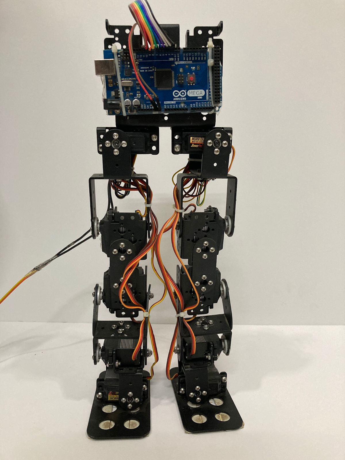
The project aims to develop a bipedal robot using Arduino which walks and moves like a human. The model consists of ten degrees of freedom, with each leg having five degrees of freedom. Both ends of the legs are connected to the torso. The Torso is a rigid body. This robot can move in a straight line in any direction using the concepts of inverse kinematics.

Arduino: We used Arduino to interact with hardware and software. It helps to control an element, to read the information from a source, and convert the information into action.
We used Arduino Mega because its bigger flash memory of 256kb gives it 8x more memory space than Uno and Micro so that you can upload more hefty code. Arduino Mega comes with the most number of pins which comprises a whopping 54 Digital I/O pins (where 15 of them have PWM) and 16 Input Analog pins. Arduino Mega can easily connect with a Standard A/B USB cable, while the Micro will need a Micro-USB cable.
Servo Motor: A servo motor is a rotational or translational motor to which power is supplied by a servo amplifier and serves to apply torque or force to a mechanical system. Servo motors allow for precise control in terms of angular position, acceleration, and velocity. It uses a positive feedback system to control the motion and final position of the shaft. We control the servo motor with Pulse width modulation (PWM), which sends an electric pulse of variable width to the motor.
According to the reciprocal contact of one leg and the ground, a classical human gait cycle is composed of stance, where the foot is on the ground, and swing. In the context of biped robots, walking can be considered as a repetition of one-step motion. The motion cycle can be divided into the single support phase and the double support phase.
Single support refers to the fact that one foot holds the robot’s weight while the other foot is moving forward in the air.
To make our robot stand properly, we hung our robot with rope above the ground and tuned each servo motor. We hung it with the rope because while tuning, it may fall down and leads to hardware damage to the robot.
Walking of the robot can be described in these steps:
Forward and inverse kinematics are implemented to determine the main parameters affecting humanoid robot behavior and specify the reliable method to control motion and preserve stability. The most frequently practiced parameters to be defined are joint parameters, including required drive torques, angles, and relative twists.
Forward or configuration and inverse kinematics for humanoid-The forward kinematics problem represents the relationship between the individual joints of the robot humanoid and the position and orientation of the tool or end effector.
The parameters for the 10 DOF of the lower body can be used further for forward and inverse kinematics to generate a trajectory:
Trajectory of hip, foot and center of mass was generated for the best
stability of the biped system.
A third-order polynomial function with variable t (time) is used to describe its trajectories.
Side View-

Front View-

At first we acknowledged different motions of our robot and through that motion we planned the trajectories and find different positions of our robot.Then we used the concepts of inverse Kinematics to find different joint angles of servo motor for best possible walk.

Trajectory planning helps us in finding a time series of successive joint angles that allows moving a robot from a starting configuration towards a goal configuration in order to achieve a task.
We used different trajectory equations for the better stabilization of our robot
X = a0 + a1(t) + a2(t)2 + a3(t)3
The hip center of a biped robot is a critical point for controlling its motion. By determining the trajectory of the hip center, the robot's movement can be controlled. The trajectory can be defined as a hyperbola, an ellipse, or a straight line.
Hyperbolic Trajectory: A hyperbolic trajectory of the hip center involves moving the hip center of the robot in a pattern that resembles a hyperbola. This type of trajectory is useful for applications that require the robot to move in a controlled and agile manner. The joint angles required for the robot to move the robot by using a hyperbolic trajectory of the hip center of the robot can be calculated using inverse kinematics.
And the straight line equation helps our robot for the best possible walk.
The third-order polynomial function with variable t (time) was used for movement of the hip to the right when the robot takes its left foot off the ground. And we have used a straight-line trajectory for bringing the hip to its primary position.
The third-order polynomial function with variable t (time) was used for the movement of the hip to the left when the robot takes its right foot off the ground. And we have used a straight-line trajectory for bringing the hip to its primary position
Here also, the same concept was used for hip center trajectory as used in the right leg walking .
To stop the robot, firstly, we used the straight line trajectory to re-center the hip to its primary position and then used the third order polynomial function to put the foot also to its primary function and so once again our robot comes to its standing position.

By using inverse kinematics we find the different joint angles of each servo motor from the position of our robot for the perfect stable motion.
The joint angles was found by using the concepts shown below:

Once the trajectory pattern is determined, the required joint angles for the robot to achieve the desired motion along that trajectory can be calculated using inverse kinematics. Inverse kinematics involves using the geometric properties of the robot and the desired position or motion to calculate the required joint angles.
https://github.com/roboclub-mnnit/Humanoid-2022-23-Project
1. Basic Concepts Of Arduino:
2.Forward and Inverse Kinematics:
Lec1 - Class 1-Kinematics
Lec2 - Class 2-Kinematics
Youtube Link:
1. https://www.youtube.com/playlist?list=PLT_0lwItn0sDBE98BsbaZezflB96ws12b (Video: Video7-Video 23)
2. https://www.youtube.com/playlist?list=PLT_0lwItn0sAfi3o4xwx-fNfcnbfMrXa7 (Video:Video1-Video9)
3.Trajectory Planning
Lecture 11: Trajectory Planning
|
Name |
Branch |
Reg. no. |
|
Devendra Saini |
ME |
20213032 |
|
Abhinav Singh |
PIE |
20216004 |
|
Anu Priya |
ME |
20213059 |
Purushotam Kumar Agrawal