Status : Completed
The project is about a cell phone-controlled bot. A bot that can be operated at our fingertips using our smartphone.
arduino
wifi
IOT
Introduction
The project is about a cell phone-controlled bot. A bot that can be operated at our fingertips using our smartphone. This project consists of two parts. One is our bot (3-wheeled car), and the other is a mobile application that will control the car. We will send our smartphone's accelerometer data via Wi-Fi to the bot (ESP 01 module). And then, after getting the data, the microcontroller (Arduino UNO) will navigate the bot accordingly.
Components
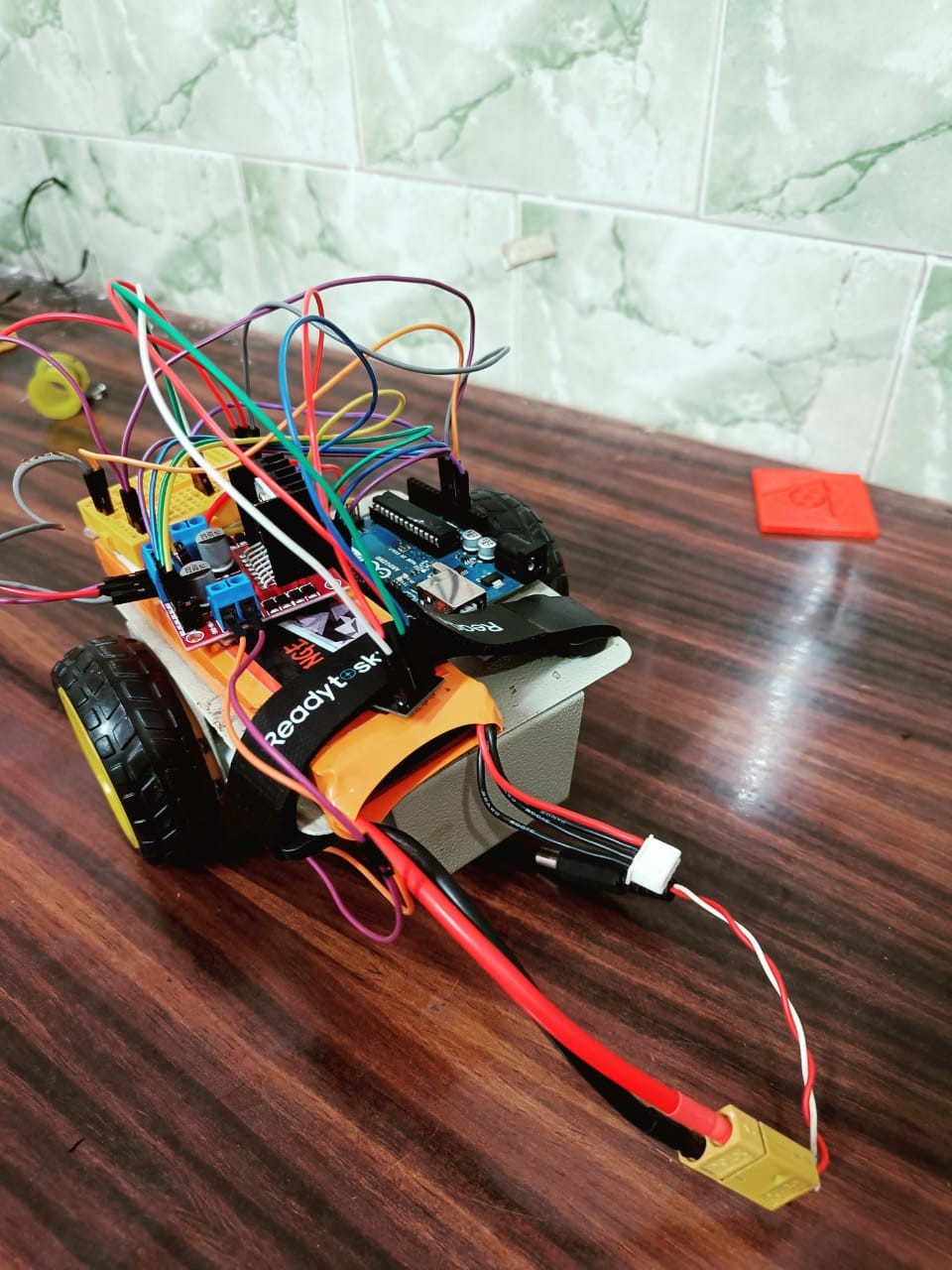
WORKING OF BOT
The project is based on the application of IoT.
The Arduino UNO is our microcontroller. We send the data from the accelerometer to ESP 01 module, which uses Wi-fi to communicate the data between the bot and the smartphone. After receiving the data from a smartphone, the Arduino UNO will navigate the bot according to the data received.
App details
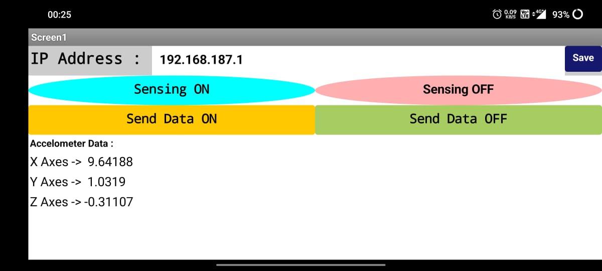
In this project, we make our app using MIT app inventor. The app is designed to take accelerometer data from the accelerometer sensor of our mobile phone and print it on the phone's screen.
Along with that, it will send the same data to the ESP 01 module every 100ms in the form of a string like -->
{ --x-axis--/--y-axis--/--z-axis--}
We have to just enter the local IP of the Node MCU and focus the switch when the WiFi module is connected.
Car details
ESP 01 will get some data through the app. Then The board microcontroller receives the data from Node MCU by Serial-communication and applies some linear equations to generate a voltage signal which varies on a scale of 0 to 5 Volts based on the magnitude and a sign of the data of the X and Y axis. The signal is then sent to the onboard motor driver (L298N), which amplifies the voltage on a scale of 0 to 12 Volts. This voltage is then sent to the motors. The same motor driver can send different data to the two motors, which helps to change the direction and speed of the car. An onboard 11.5V LiPo battery powers this car.
ESP 01 Module
The ESP8266 ESP-01 is a Wi-Fi module that allows microcontrollers access to a Wi-Fi network. This module is a self-contained SOC (System On a Chip) that doesn’t necessarily need a microcontroller to manipulate inputs and outputs as you would normally do with an Arduino, for example, because the ESP-01 acts as a small computer. Depending on the version of the ESP8266, it is possible to have up to 9 GPIOs (General Purpose Input Output). Thus, we can give a microcontroller internet access like the Wi-Fi shield does to the Arduino, or we can simply program the ESP8266 to have access to a Wi-Fi network and act as a microcontroller as well. This makes the ESP8266 very versatile, saving you money and space in your projects—configuration to upload Code in ESP01
Code details and Implementation
1. Arduino Code
Arduino programming is a subset of C++ programming language with additional functions and methods. Arduino code, also known as Sketch, is written inside the IDE (Arduino Software), which compiles the code and converts it into machine language.
Following are some steps needed to run Arduino code:
Step 1: Once the Arduino board is connected, it will automatically install the necessary drivers needed and select the port at which it is connected.
Step 2: Connection is established between the Arduino board and PC. It’s time to upload an Arduino sketch.
Once our code is compiled, we will see the message Done compiling in the output window.
Step 3: The last step is to upload this sketch in Arduino. To do this click the right-pointing arrow known as the Upload button present on the right side of the verify button. Once the upload is finished, a Done Uploading message will appear in the output window.
2. ESP01 Code
Connect the esp01 module to Arduino as shown in the figure above
Step 1: To upload the code connect the Rx of Arduino to Rx of Esp01 and Tx of Arduino to Tx of Esp01.
Step 2: Change the module from Arduino Uno to Generic Esp8266 module.
Step 3: First verify the code and then upload it in the Esp01 module as did earlier.
Step 4: After uploading the code, remove the reset pin connection from the ground. If a blue light blinks in the Esp01 module, then the esp module has been connected to the wifi hotspot mentioned in the code. If the blue light does not blink, try removing the CH_PD pin and then connecting it again. The same can be done if there is a connecting problem while uploading the code.
Step 5: After the code is uploaded, the Rx pin of esp01 is connected to Tx pin of Arduino and the Tx pin of esp01 is connected to the Rx pin of Arduino.
CONTRIBUTORS
MENTORS