
Status : Completed
Tags: ESC BLDC_simulation Arduino_programming
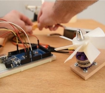
Documentation on BLDC and it's Characteristics along with operation through arduino and ESC
Arduino
ESC
BLDC
A BLDC motor accomplishes commutation electronically using rotor position feedback to determine when to switch the current. Feedback usually entails an attached Hall sensor or a rotary encoder.
The stator windings work in conjunction with permanent magnets on the rotor to generate a nearly uniform flux density in the air gap. This permits the stator coils to be driven by a constant DC voltage (hence the name brushless DC), which simply switches from one stator coil to the next to generate an AC voltage waveform with a trapezoidal shape.
There are three classifications of the BLDC motor: single-phase, two-phase and three-phase. This discussion assumes that the stator for each type has the same number of windings. The single-phase and three-phase motors are the most widely used.The BLDC motor is widely used in applications including appliances, automotive, aerospace, consumer, medical, automated industrial equipment and instrumentation.
The BLDC motor is electrically commutated by power switches instead of brushes. Compared with a brushed DC motor or an induction motor, the BLDC motor has many advantages: